Technical Drawing Symbols for Piping Plans
What is Pipe Isometric Drawing?
Once the three-dimensional (3D) model has been established in pipe design software similar PDS, PDMS, or SP3D, Pipe Designers/Engineers demand to convey that information to the yard for fabrication and site for Construction. The transferred data must accept to be sufficient for the fabricator with the vision of what is to be made and how the piping should exist connected with other elements, with exact dimensions and complete build/Bill of materials (BOM). This is where Piping Isometric Drawings play a magnificent role. So pipe isometrics are directly used for the following situations:
- For Construction Services
- For marking upwardly deviation during site modifications/ as-builting.
- For reference every bit Stress Analysis model built upwardly and last stress mark up for updating stress requirements.
Piping isometrics indirectly helps to calculate many parameters required during project execution similar:
- Inch Meter can be estimated every bit Length of pipe (in meter) x Size of pipe ( in inch )
- Inch Dia is calculated as Size of Pipe joint ( in inch) x No, of Joints
- Pipe Weight is calculated as π x bore of the pipe (in m) 10 length (in yard) x thickness (in mm) x density of pipe material. Density of CS = 7.85 g/cm3
- The volume of Water required for hydro testing is estimated as π ten {Pipe ID (in meter)}² x Length of Pipage
- Insulation Area (in m²) can exist establish equally [π(Pipe OD+ insulation thickness)] (all in meter) x Length of Piping (in meter)
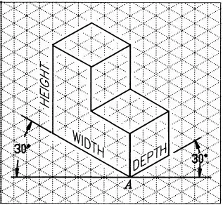
By definition, Isometric drawings are a pictorial representation that combines height-width-depth/length into a single view with thirty degrees from its horizontal plane as shown in the below fastened image.
Features of Pipe Isometric Cartoon
Isometric Drawing is a two dimensional (2D) cartoon that represents the 3D pipe system. The of import features are
- It is not fatigued to the scale, just it is proportionate with verbal dimensions represented.
- Pipes are drawn with a unmarried line irrespective of the line sizes, every bit well every bit the other configurations such every bit reducers, flanges, and valves.
- pipes are shown in the aforementioned size. The actual sizes are notified in Pecker of Textile, tagging, phone call-out, or notes.
- A pipage isometric drawing provides all the required information like:
- Pipe Line Number
- Continuation isometric number
- Flow management
- Piping dimensions
- Pipe articulation types, weld types
- Flange and valve types
- Equipment connectedness details
- Pipe and Component descriptions with size, quantity, and fabric codes
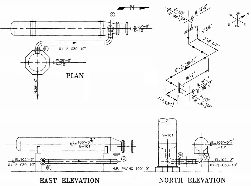
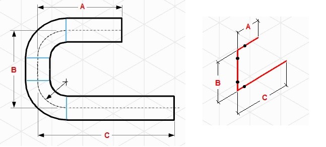
Piping Isometric drawings are pop because of their simplicity yet efficiency to convey complex data. The following figure gives an example of how i Isometric drawing can stand for three orthographic drawings. That is just a simple piping drawing. Imagine complex design and yet orthographic drawings are used for construction, that is actually a headache.
In earlier days, Isometric drawings were hand-fatigued. With the innovation and advocacy of the digital historic period, isometrics are fatigued by AutoCAD/Microstation software. In contempo days, the 3D models could automatically extract the Isometric with a single click of a mouse.
How to Read Piping Isometric Drawings?
1. First, imagine that the piping organization is built in a box. This basic imagination is required for the piping to have an beginning. And then, it volition help you to imagine, how the piping configuration volition look like as it travels.
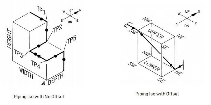
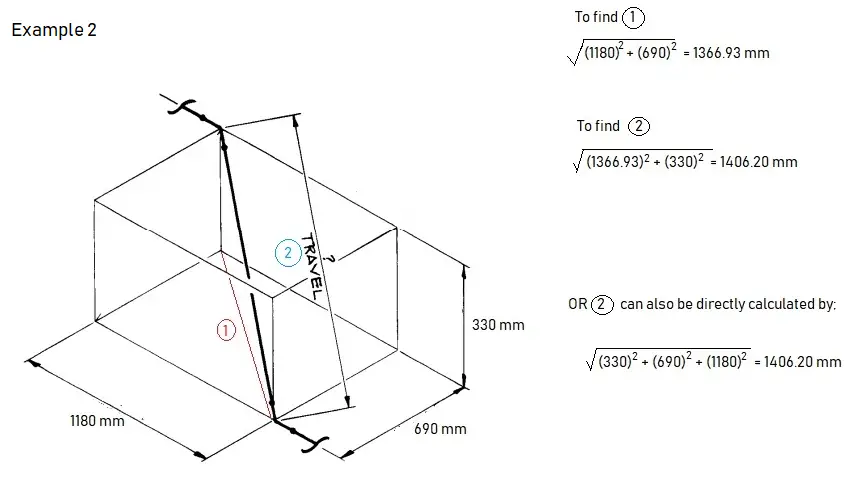
two.Offset happens when the piping turns to whatsoever angle other than ninety-caste or to conform odd nozzle's location or tie in indicate connections. A popular utilize is a 45-degree elbow and this is used extensively in piping pattern. In such cases, piping design may land on Northeast, Southeast, Northwest, or Southwest axes. In order to bank check the dimension of pipe length with offset, mutual Pythagoras's theorem and Trigonometric rule can be used. A sample adding is shown below as a reference-
Example of length adding in Pipage Isometric
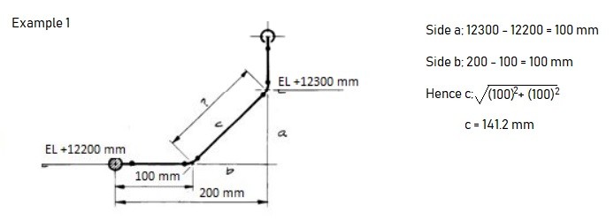
Example of offset
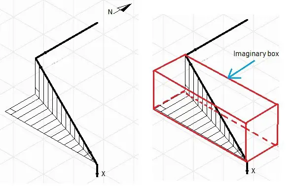
If you happened to accept difficulties in reading the first, try to draw the imaginary box. It could assist you in having a meliorate understanding of which axes the pipe travel and how the piping should await like. In the example given, take the menstruation from '10', the pipage goes up; then up-northwest; then north. Every bit you get forth with Iso a lot, things will come up naturally.
3. A North arrow is provided in all piping isometrics to inform the location of the piping system in piping/ full general organization drawing.
4. The piping isometrics besides hascoordinates & height detailed information to verify the exact length of pipe in horizontal and vertical axes respectively. The dimensions in Isometric drawings are measured from the pipe centreline and not from the outer diameter of the pipe (refer to the image attached beneath for reference).
With the advancement of technology, there could be minimum or even null possibilities that the Due north arrow, coordinates, and elevation in Isometric would differ from the piping organization; hence the dimensions and MTO should match exactly if the source 3D model is the same.
Still, It is always improve to check and verify as there could be some issues with the modeling itself that may cause discrepancies in material and quantity. For example, if double piping is modeled by mistake, it volition read the double quantity of fabric.
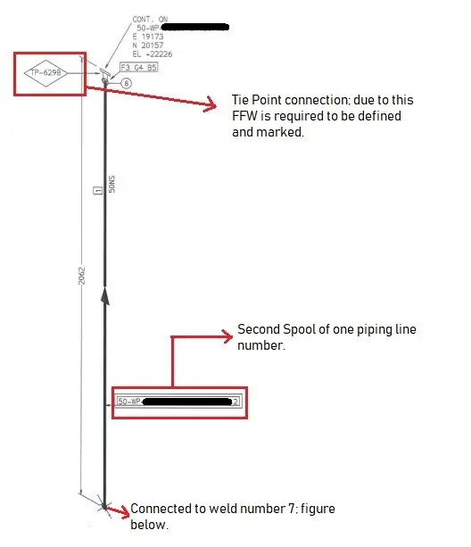
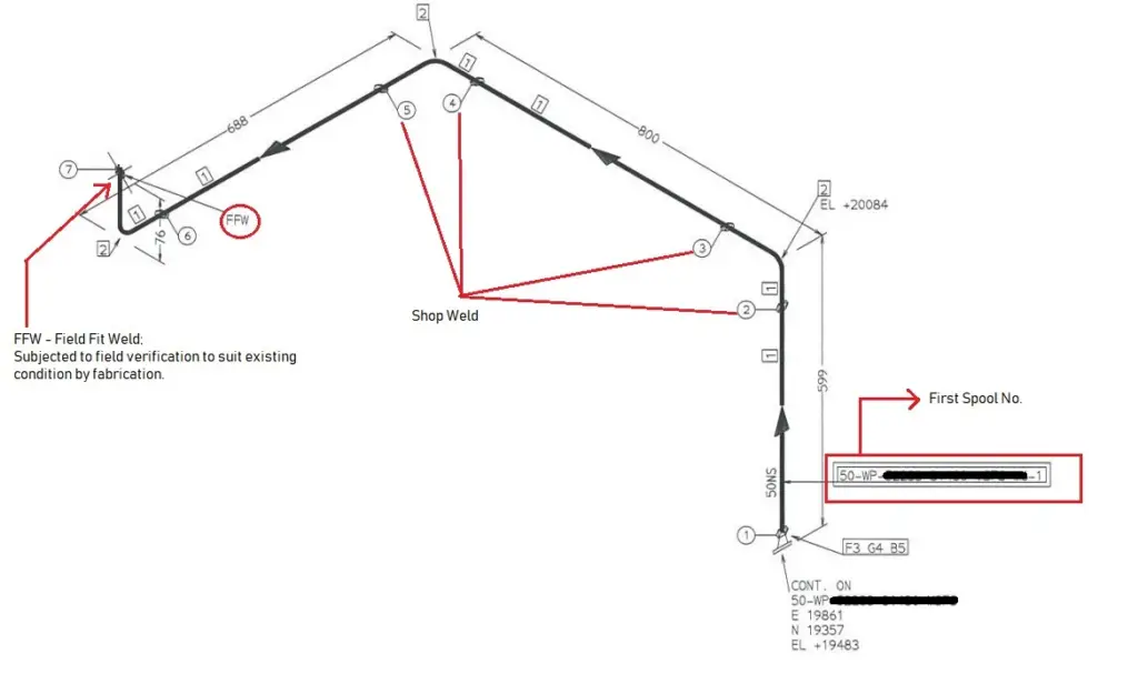
5. Isometric drawings likewise inform which piping should be constructed at the fabrication shop and which should exist assembled at the construction/platform field itself. The consummate pipe system is separated into pieces that are transported to the site for erection. These pocket-size pipe pieces are termed piping spools. One sheet of Isometric drawing normally has few spools.
Every weld that is assembled between spools at the construction site is termed afield weld (FW). There is one more blazon of weld that is known as field-fit weld (FFW). This FFW is defined by the designer if he/she could foresee that the spool might require some aligning before the final fit-upwardly, then at the location of FFW has been marked, it will be given some piping length tolerance (commonly 150-300mm). Usually, FFW will occur at the nozzle of equipment or tie-in locations.
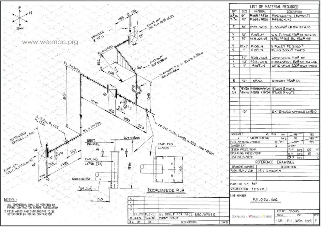
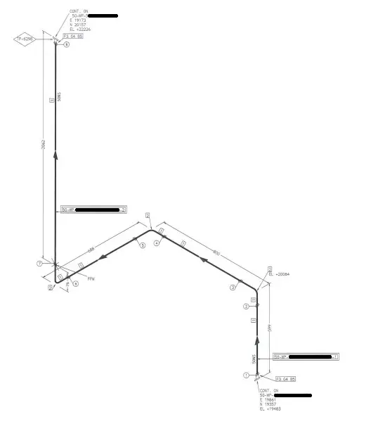
The whole assembled piping volition wait like the following later information technology is assembled at the field.
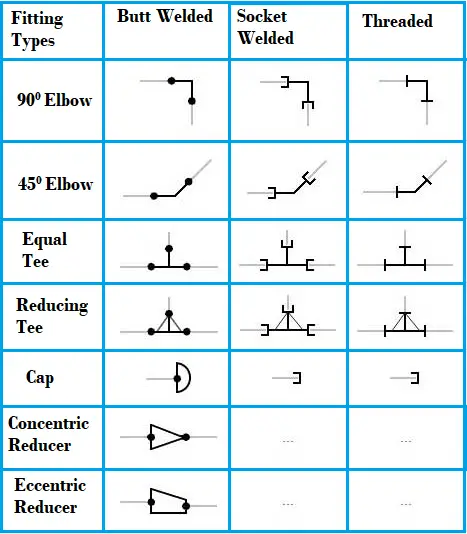
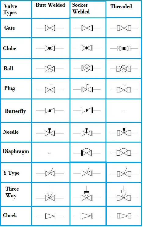
Piping isometric drawing symbols
For reading and understanding a piping isometric cartoon, ane should learn the piping isometric drawing symbols thoroughly. Usually, all these piping and pipeline cartoon symbols are abiding and does non vary much from one organization to the another. Knowing the pipage cartoon symbols will provide various information like:
- Type of Pipe Joint: Piping and pipeline drawing symbols throw lights on the type of joint like Buttweld, socket weld, or Threaded.
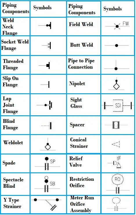
- Type of piping Components: Isometric cartoon piping symbols serves as a set reference for blazon of fittings and components.
- Instrument items: Knowing the piping isometric symbols will help in recognizing the musical instrument and special piping items in the isometric.
- Equipment Connection: Equipment connected to a piping organization is likewise understood with pipage symbols.
- Knowing pipe symbols for isometric drawing is useful in preparing MTO/BOM.
Commonly used pipe isometric drawing symbols are shown below for reference purpose
Video Tutorial of Basics of Piping Isometric Cartoon
The following video tutorial on the basics of pipe isometric drawing will analyze some of your doubts.
Some more Resources for you lot…
Salient Points to check while reviewing Piping Isometric Drawings
Preparation of Pipage Isometrics
Types of Piping Drawings
References
- Credit to other sources: svlele.com, wermac.org, pipingengineer.org, thepiping.com, spedweb.com, enggcyclopedia.com, rishabheng.com
- https://world wide web.sciencedirect.com/topics/engineering/piping-isometric

Source: https://whatispiping.com/basic-piping-isometric-drawings/
0 Response to "Technical Drawing Symbols for Piping Plans"
Post a Comment